
 عربى
عربى

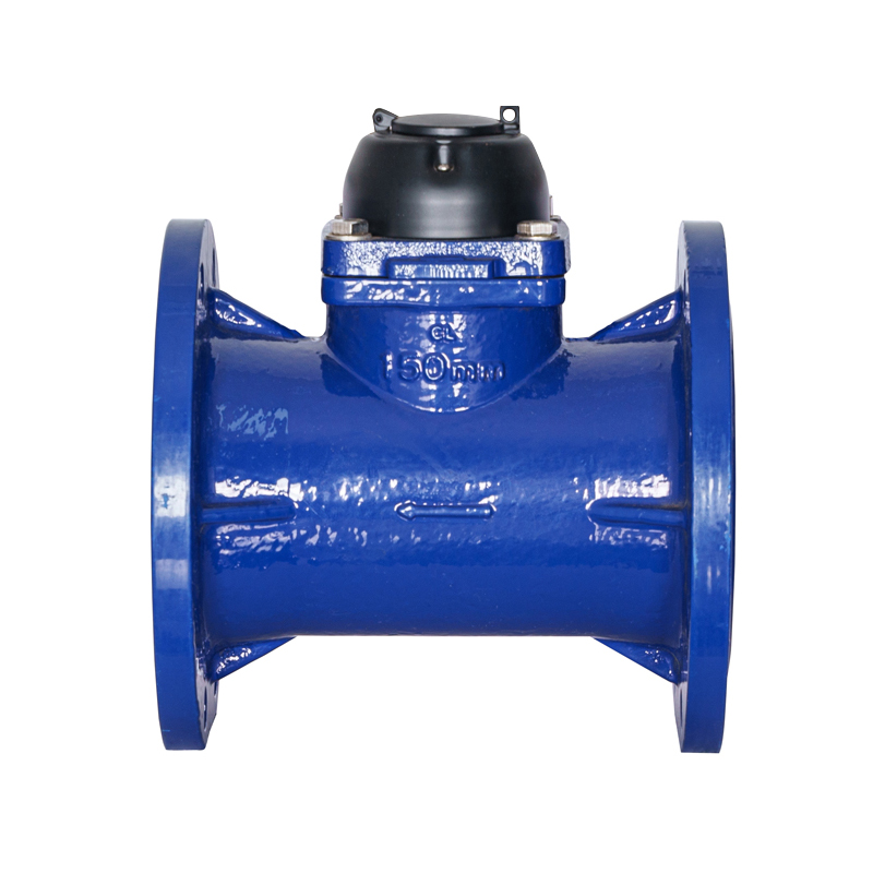
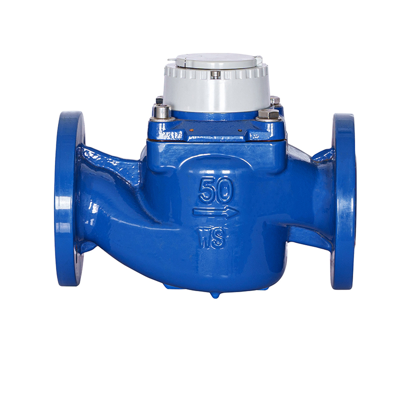
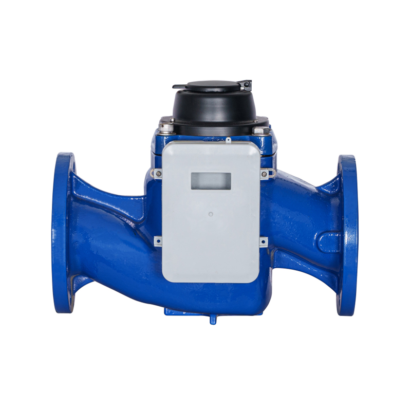
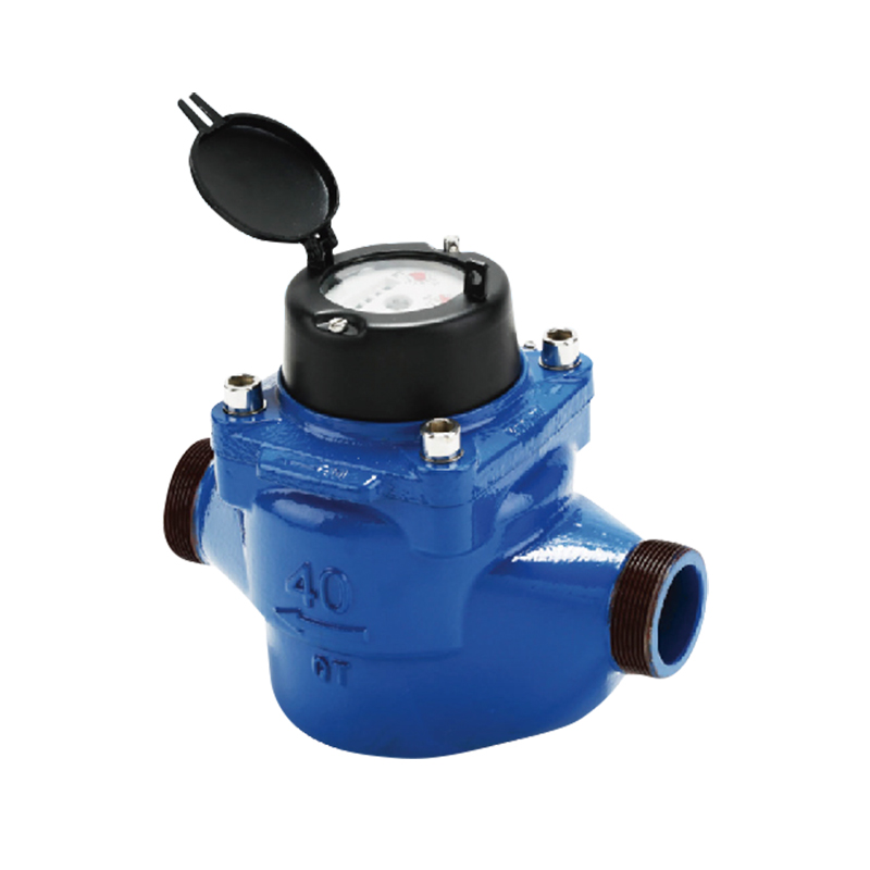
Managing large-scale agricultural operations, commercial turf networks, and industrial water distribution lines requires highly accurate and rugged flow measurement tools. The industrial-grade WI irrigation water meter serves as the primary tool for checking water usage, verifying system efficiency, and meeting regional environmental rules. Utilizing an axial-flow Woltman turbine mechanism combined with an isolated dry-dial register, this specific meter configuration handles high-volume raw water streams containing suspended sediment, organic matter, and particulate debris without jamming, losing mechanical calibration, or dropping inline line pressure.
Mechanical Kinetic Principles of the Woltman Turbine Assembly
The operational foundation of a WI irrigation water meter relies on a horizontal-axis Woltman turbine impeller positioned directly within the path of the flowing fluid. Unlike residential meters that use nutating discs or oscillating pistons—which can choke or jam when exposed to sandy or dirty water—the WI configuration features a wide, open fluid channel designed to let suspended solids pass through easily.
When water enters the cast-iron body of the meter, it passes through an integrated flow-straightening vane assembly. This intake geometry conditions the incoming stream, converting turbulent whirlpools and irregular currents into a smooth, parallel fluid path. The moving water impacts the helical blades of the polymer turbine, turning it at a speed that matches the flow velocity. The rotation of this impeller connects directly to a sealed, dust-proof magnetic coupling drive, transferring the rotational data smoothly up into the dry-dial register housing without any mechanical shaft penetrations.
The Dynamic Function of Isolated Dry-Dial Registers
By isolating the gear trains and odometer counters inside a vacuum-sealed, nitrogen-filled glass enclosure, the meter prevents internal fogging, corrosion, and sediment buildup. Water never enters the display window, ensuring the dial face remains perfectly clear for manual field inspections or automated optical scanning systems over decades of continuous exposure to damp fields and fertilizer sprays.
Metallurgical Framework and Environmental Protection Ratings
Because irrigation networks operate in rough, outdoor conditions, the external body of the meter must withstand high mechanical stresses, soil movement, and temperature spikes. The main body casting is typically poured from heavy-walled ductile iron or epoxy-coated cast carbon steel, providing a rugged shell that resists cracking when lines expand or contract from thermal shifts.
To guard against the aggressive chemicals used in modern liquid fertilizers, herbicides, and high-salinity well water, the interior and exterior iron surfaces are protected by a thick layer of fusion-bonded epoxy. This coating achieves a hardness rating exceeding 250 microns in thickness, forming a tough barrier that prevents rust, pitting, and mineral scale buildup inside the flow tube. The internal turbine shaft spins on premium tungsten carbide or polished ceramic bearings, which maintain low friction coefficients and resist wear even when filtering fine abrasive quartz sand through the line.
Hermetic Seals and IP68 Compliance Architecture
The upper counting assembly features an IP68 ingress protection classification. This ensures the dial module can remain submerged under up to 2.0 meters of standing surface water inside sub-surface concrete pits for weeks at a time without allowing a single drop of moisture to enter the magnetic transmission zone.
Performance Specifications and Fluid Capacity Metrics
Selecting the correct size of a WI irrigation water meter requires matching the expected flow rate of the pump station to the optimal measurement accuracy range of the turbine assembly. Oversizing a meter will cause it to miss low-flow volumes, while undersizing creates excessive backpressure and can spin the turbine past its mechanical limits, wearing out the bearings prematurely.
The table below outlines the standard mechanical dimensions, flow capacities, and accuracy parameters for different flanged sizes of industrial WI irrigation water meters:
| Nominal Flange Size | Minimum Flow Threshold ($Q_1$) | Nominal Flow Target ($Q_3$) | Maximum Peak Capacity ($Q_4$) | Head Pressure Loss ($\Delta P$) |
|---|---|---|---|---|
| DN50 (2-Inch) Connection | 2.80 Cubic Meters / Hour | 35.0 Cubic Meters / Hour | 50.0 $m^3/h$ | < 0.10 Bar at $Q_3$ |
| DN80 (3-Inch) Connection | 5.20 Cubic Meters / Hour | 65.0 Cubic Meters / Hour | 90.0 $m^3/h$ | < 0.10 Bar at $Q_3$ |
| DN100 (4-Inch) Connection | 8.00 Cubic Meters / Hour | 100.0 Cubic Meters / Hour | 125.0 $m^3/h$ | < 0.15 Bar at $Q_3$ |
| DN150 (6-Inch) Connection | 20.00 Cubic Meters / Hour | 250.0 Cubic Meters / Hour | 312.5 $m^3/h$ | < 0.15 Bar at $Q_3$ |
Fluid Mechanics, Straight-Run Limits, and Flow Distortions
To maintain an accuracy rating of within +/-2% under full flow parameters, the fluid entering the turbine must be free of swirls, asymmetrical velocity profiles, and air pockets. When water travels through elbows, partially closed valves, or pumps, it develops a chaotic spiral motion that can distort flow data if the meter is placed too close to these turbulence sources.
To prevent these tracking errors, engineers follow strict upstream and downstream piping guidelines, often described as the pipe diameter (D) rule. A standard installation requires a straight run of continuous pipe measuring at least 5D to 10D upstream from the meter flange, and at least 2D to 5D of straight pipe downstream. These straight sections give fluid turbulence space to settle out naturally, ensuring a balanced, even flow profile impacts the turbine blades for accurate readings.
Managing Air Entrainment and Line Priming
Air bubbles trapped in irrigation lines represent another common cause of measurement errors. Because a turbine counts revolutions based on volume rather than mass, compressed air pockets passing through the flow tube will spin the impeller at high speeds, leading to artificially inflated consumption readings. Installing automatic air release valves upstream from the meter vents these trapped gas bubbles safely, protecting the accuracy of the data.
Precision Field Installation and Calibration Sequencing
Installing a WI irrigation water meter into a mainline delivery network requires following precise mechanical steps. Poor installation habits can distort flow profiles, cause flange leaks, or damage internal components.
- Verify Pipeline Directional Alignment: Inspect the outer casting to find the cast flow arrow indicating the correct fluid path. The meter must be aligned so that the internal turbine faces directly into the incoming stream; installing a meter backward blocks the register from counting and can damage the internal gearing.
- Flush the Piping Infrastructure: Prior to lowering the meter into position, run the main pump at full capacity for several minutes to flush out any welding slag, dirt clumps, stone chips, or weeds left inside the pipe during construction, preventing these items from damaging the turbine blades during startup.
- Seat Flange Gaskets and Tighten Bolts: Place premium, steel-reinforced EPDM gaskets between the mating flanges. Insert high-tensile grade bolts through the flange holes and use a calibrated torque wrench to tighten the nuts in a star-pattern sequence, ensuring even pressure across the joint to prevent leaks and stress fractures.
- Ensure a Full-Pipe Flow Configuration: Position the meter line lower than the main discharge point, or incorporate a raised U-bend downstream from the outlet. This elevation difference ensures the meter body remains completely flooded with water during operation; if the pipe runs partially empty, the turbine will under-read consumption values significantly.
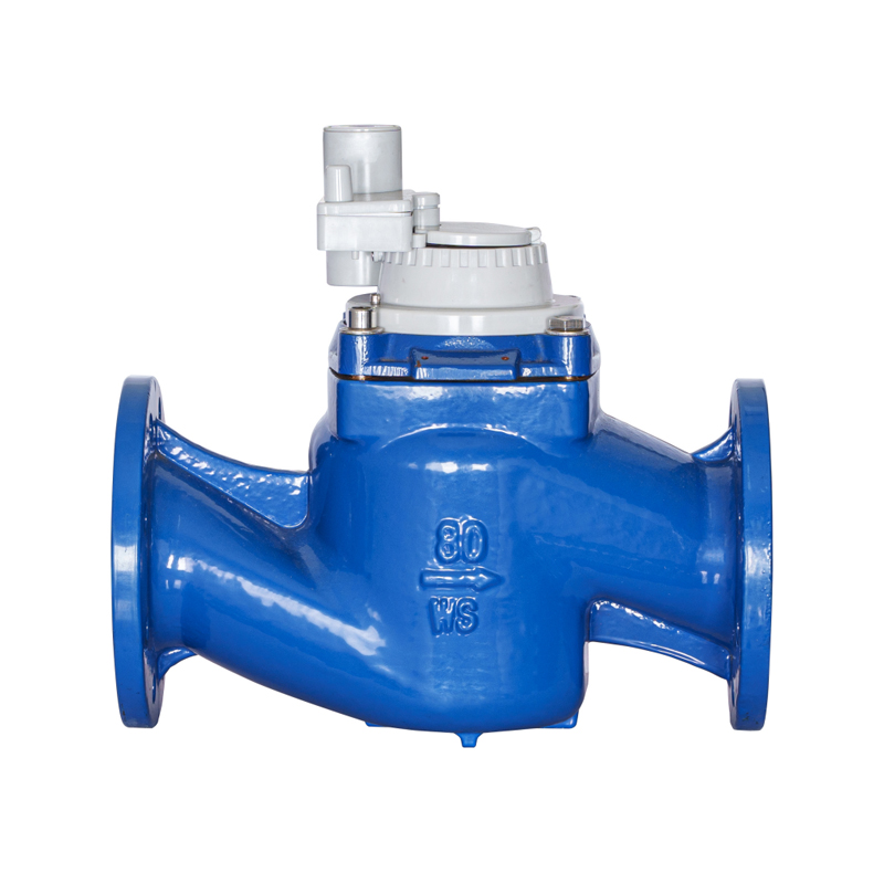
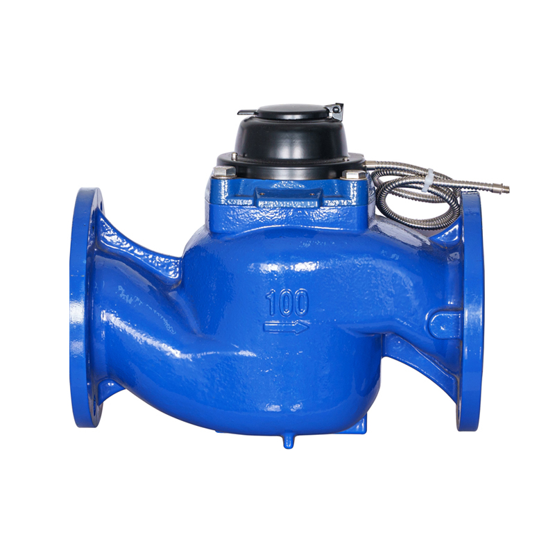
- Wire Advanced Pulse Output Modules: Snap an electronic pulse transmitter sensor into the pre-molded slot on the register cover plate. Connect the sensor leads to an external telemetry RTU box or data logger system, allowing the team to stream flow data back to a central tracking database.
Telemetry Systems and Smart Grid Pulse Communication
Modern agricultural operations are moving away from manual odometer readings, upgrading instead to automated, real-time data tracking networks. The WI irrigation water meter adapts to this digital transition through integrated pulse output components.
The dry-dial register features a tiny target magnet mounted on one of its high-speed internal indicator needles. As this needle spins past a sensor port on the glass face, it trips an external dry-contact Reed switch or a high-sensitivity solid-state Hall Effect sensor. This interaction sends an electrical signal down the wire to a data logger, translating to a set volume metric—such as 1 pulse per 100 liters or 1 pulse per cubic meter of water. These electronic pulses are broadcast over cellular links or long-range radio networks (LoRaWAN), giving farm managers up-to-the-minute flow updates on their smartphones or office computers.
This automated data stream allows managers to identify hidden problems instantly. For example, if the telemetry log shows a steady, unexpected flow rate in the middle of the night when valves should be locked tight, it indicates a major line break or stuck valve downstream, helping the team respond quickly to prevent crop damage and save water.
Field Maintenance, Diagnostics, and Troubleshooting Routines
Even with a rugged design, a water meter working with unfiltered canal or river water can experience performance drifts or mechanical wear over years of field service.
If a meter begins to under-report consumption values consistently, the issue is often caused by long fibrous weeds or thin plastic mulch ribbons wrapping around the impeller hub. This debris creates mechanical drag that slows down the turbine blades. To fix this, technicians do not need to cut the entire meter body out of the line; instead, they can simply remove the top cover bolts and lift the entire internal turbine insert cleanly out of the casting. This design allows maintenance teams to clean out debris, inspect the bearings, and slip a fresh, factory-calibrated core insert back into place in minutes, minimizing system downtime.
Another common problem is a complete loss of pulse signals while the mechanical dial continues to turn normally. This issue usually points to a failed Reed switch, often caused by a voltage spike from a nearby lightning strike. Technicians can swap out the external clip-on sensor module without opening the dry-dial capsule or shutting off the main water valve, quickly restoring digital data tracking while keeping the system running safely.