What Makes the High Precision Vertical Spiral Wing Detachable Water Meter a Benchmark for Metrological Superiority and Performance Stability in Modern Water Management?
The development of the High Precision Vertical Spiral Wing Detachable Water Meter marks a significant advancement in bulk and mainline flow measurement technology. This innovative High Precision Vertical Spiral Wing Detachable Water Meter product design is founded upon established German technological principles and has been meticulously refined and adapted to address the specific and challenging water environment prevalent in China. The resulting instrument, the High Precision Vertical Spiral Wing Detachable Water Meter, exhibits world class performance, setting a new industry standard for accuracy and operational resilience, particularly in dynamic flow conditions.
Engineering and Metrological Superiority: Redefining Flow Detection Accuracy
The core innovation of the High Precision Vertical Spiral Wing Detachable Water Meter lies in its unique fusion of proven hydraulic concepts, effectively bridging the gap between two traditionally separate meter designs: the horizontal spiral wing water meter and the rotary wing water meter. This hybrid approach leverages the best attributes of both, resulting in a full flow detection system that offers unprecedented measurement precision.
Unique Hydraulic Flow Path and Accuracy Benefits
The High Precision Vertical Spiral Wing Detachable Water Meter employs an axial measured water flow path, characterized by a low inlet and a high outlet. This vertical alignment is crucial for several performance advantages inherent to the High Precision Vertical Spiral Wing Detachable Water Meter design:
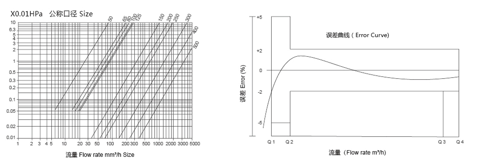
Full Flow Detection: Unlike older designs that may measure only a portion of the cross sectional area, this High Precision Vertical Spiral Wing Detachable Water Meter ensures that the entire volume of water passing through the tube contributes to the rotational force of the spiral wing. This complete interaction minimizes measurement error caused by flow stratification or uneven velocity profiles, especially important in large diameter pipes.
Axial Flow Dynamics: The water flow aligns directly with the axis of the vertical turbine. This minimizes radial thrust and wear on the bearing system, which in turn leads to greater mechanical stability and a prolonged period of accurate operation. The axial movement of the fluid promotes a smoother, more laminar engagement with the spiral wing blades of the High Precision Vertical Spiral Wing Detachable Water Meter.
Superior Low Flow Rate Accuracy: This is perhaps the most crucial metrological advantage of the High Precision Vertical Spiral Wing Detachable Water Meter. The design ensures that the large effective area of the vertical spiral wing responds effectively to minimal kinetic energy in the water stream. At very low flow rates, where most water meters struggle to overcome static friction and accurately register consumption, the structure of this High Precision Vertical Spiral Wing Detachable Water Meter demonstrates an accuracy that is demonstrably higher than other types of water meters, including traditional rotary types. This level of precision at low flow rates is vital for accurately accounting for night time consumption and leakage, thereby supporting water conservation efforts and revenue protection.
Optimized Performance for Fluctuating Conditions
The market requires water meters that can maintain their accuracy across a vast range of flow conditions, from trickle leaks to peak demand surges. The inherent stability and design of the vertical spiral wing make the High Precision Vertical Spiral Wing Detachable Water Meter exceptionally suitable for water metering in situations that exhibit significant and frequent changes in flow rate. This product offers a wide range capability, suitable for situations with large flow changes.
Wide Dynamic Range: The optimized rotational characteristics of the spiral wing allow the High Precision Vertical Spiral Wing Detachable Water Meter to function effectively across a very wide metering range. This wide range capability means a single installed High Precision Vertical Spiral Wing Detachable Water Meter can reliably measure both the smallest essential flows and the highest rated flows without compromising accuracy at either extreme.
Internal Straightening and Stabilization: The vertical orientation and specialized internal component geometry contribute to a natural flow conditioning effect within the High Precision Vertical Spiral Wing Detachable Water Meter. This flow stabilization allows the meter to achieve its specified high accuracy without the need for the installer to incorporate costly or space consuming straight pipe sections before or after the meter during installation, drastically simplifying field deployment and reducing overall infrastructure costs.
Internal Adjustment Structure: An advanced internal adjustment structure is incorporated into the movement of the High Precision Vertical Spiral Wing Detachable Water Meter. This structure serves the dual purpose of factory calibration fine tuning and, critically, acting as an effective mechanism to prevent unauthorized meter adjustment after installation. This security feature is paramount for maintaining the integrity of billing and ensuring fair revenue measurement for water utilities utilizing the High Precision Vertical Spiral Wing Detachable Water Meter.
Durability and Material Specification
The operational lifespan of the High Precision Vertical Spiral Wing Detachable Water Meter is heavily dependent on its ability to withstand constant fluid movement, particulate abrasion, and chemical corrosion. Different calibers correspond to different movements, and all utilize full flow detection, ensuring the consistent high measurement accuracy that defines the High Precision Vertical Spiral Wing Detachable Water Meter.
Integrated Stainless Steel Filter: A key design element of the High Precision Vertical Spiral Wing Detachable Water Meter, particularly for the challenging environment in China, is the inclusion of a built in stainless steel filter. This robust filter design protects the sensitive measuring mechanism from solid debris and foreign particles commonly found in municipal water supplies. By preventing damage to the spiral wing and bearing system, this filter is instrumental in ensuring the long term stable operation of the product.
High Wear Resistance Bearing System: The reliability of any mechanical water meter pivots on its bearing system. This High Precision Vertical Spiral Wing Detachable Water Meter features a high wear resistance bearing system utilizing advanced materials such as ceramic or high grade polymers that exhibit exceptionally low friction and high resilience to chemical and particulate contamination. This system ensures the long term stability and reliability of the product, directly leading to a significantly improved flow rate of the product over its service life.
Superior Performance Benchmark: When comparing overall operational metrics, the overall performance is better than the LXS rotary wing water meter, establishing this High Precision Vertical Spiral Wing Detachable Water Meter as the superior choice for demanding applications.
How Does the Detachable Vertical Spiral Wing Design of the High Precision Vertical Spiral Wing Detachable Water Meter Ensure Maintenance Accessibility and Data Integrity?
The design philosophy behind the High Precision Vertical Spiral Wing Detachable Water Meter goes beyond simple measurement, focusing equally on minimizing the lifetime cost of ownership through simplified maintenance, enhanced durability, and versatile data output options. We, as a specialized manufacturer and factory of the High Precision Vertical Spiral Wing Detachable Water Meter, prioritize user experience and system longevity.
Design Features, Durability, and Maintenance Accessibility
Maintenance and Lifespan Enhancement Features
Accessibility and protection are built into the core structure of the High Precision Vertical Spiral Wing Detachable Water Meter.
Detachable Movement Structure: A fundamental characteristic of the High Precision Vertical Spiral Wing Detachable Water Meter is the adoption of a detachable movement structure for easy maintenance. This allows the entire metering mechanism, including the spiral wing, bearings, and counter, to be removed from the main flow casing without the need to decouple the entire meter body from the pipeline. This feature significantly reduces downtime, simplifies calibration checks, and lowers labor costs associated with servicing, ensuring that the High Precision Vertical Spiral Wing Detachable Water Meter can be maintained efficiently in the field.
Advanced Case Protection:
To combat environmental factors, the High Precision Vertical Spiral Wing Detachable Water Meter employs industry leading technology.
Advanced Thermal Spraying Technology: The watch case of the High Precision Vertical Spiral Wing Detachable Water Meter adopts advanced thermal spraying technology in the industry to enhance its protective properties. This process involves applying a dense, highly adherent protective coating—often metallic or ceramic—to the exterior of the meter body. This thick layer dramatically improves the corrosion resistance of the watch case and extends its service life by providing a superior barrier against external chemical agents and physical damage.
Optional Anti Pry Protective Cover: For installations in vulnerable or public areas, the High Precision Vertical Spiral Wing Detachable Water Meter can be equipped with an optional anti pry protective cover. This robust outer casing deters tampering and protects the meter body from unauthorized access or deliberate damage, safeguarding the investment and data integrity of the High Precision Vertical Spiral Wing Detachable Water Meter.
Versatile Counter and Data Output Technologies
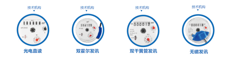
The High Precision Vertical Spiral Wing Detachable Water Meter offers a range of counter configurations and signal output capabilities to integrate seamlessly with modern Automatic Meter Reading infrastructure.
Magnetic Transmission Dry Structure:
An optional configuration of the High Precision Vertical Spiral Wing Detachable Water Meter features a magnetic transmission dry structure. This system uses magnetic coupling between the turbine and the counter, physically isolating the counting mechanism from the water flow. This design ensures cleanliness and a clear display over the meter's life. The counter remains dry, preventing fogging or contamination that could obscure the reading. This configuration is further enhanced by:
Configurable Message Counter with Multiple Pulses: This allows for digital connectivity, providing high resolution data proportional to the volume of water passed.
Signal Output Options: A wide range of electrical signal outputs are available for the High Precision Vertical Spiral Wing Detachable Water Meter, including single, double, or triple reed switches, metal sensors, and Treyer elements, allowing for flexible integration with various remote reading systems.
Copper Sealed Dry Meter:
Alternatively, the High Precision Vertical Spiral Wing Detachable Water Meter can be configured with a configurable copper sealed dry meter counting device. The copper sealing offers superior long term protection against moisture ingress and tampering, while maintaining the benefits of a dry counter. This configuration achieves an Ingress Protection level 68. Ingress Protection level 68 signifies that the High Precision Vertical Spiral Wing Detachable Water Meter is completely protected against dust ingress and can withstand long periods of immersion in water under pressure, making it ideal for installation in flooded pits or underground chambers without risk of failure.
Wet Liquid Seal Structure:
For environments with complex magnetic interference, an optional wet liquid seal structure is available for the High Precision Vertical Spiral Wing Detachable Water Meter. In this design, the counter is submerged in a specially purified liquid, which naturally keeps the reading window clean, clear, and provides an additional layer of protection. Crucially, the wet liquid seal structure ensures that the High Precision Vertical Spiral Wing Detachable Water Meter’s operation and reading are not affected by any external magnetism field interference, maintaining accuracy even when unauthorized magnetic devices are placed near the meter. The liquid seal counter can be optionally equipped with three Hall remote transmission components for highly reliable digital signal generation, providing redundancy and accuracy in data transmission for the High Precision Vertical Spiral Wing Detachable Water Meter.
Advanced Remote Reading Capabilities:
Catering to smart water networks, the High Precision Vertical Spiral Wing Detachable Water Meter offers advanced digital communication options:
Passive Direct Reading Counter: This counter can be configured for optional passive direct reading using industry standard interfaces.
RS 485 or M BUS Standard Interface: Communication is facilitated via the RS 485 industrial standard serial communication protocol or the M BUS meter bus standard protocol. The inclusion of these standard interfaces ensures seamless integration of the High Precision Vertical Spiral Wing Detachable Water Meter into existing and future Automatic Meter Reading and Supervisory Control And Data Acquisition systems, providing real time, precise data for billing and network management purposes.
In summary, the design and manufacturing of the High Precision Vertical Spiral Wing Detachable Water Meter represents a complete lifecycle solution. By synthesizing specialized hydraulic principles with advanced material science, and coupling this robust core with diverse, highly secure communication options, the High Precision Vertical Spiral Wing Detachable Water Meter delivers not only unparalleled accuracy at every flow regime but also guarantees long term service life and cost effective maintenance, solidifying its position as the premium choice for modern water metering applications.

 عربى
عربى