
 عربى
عربى

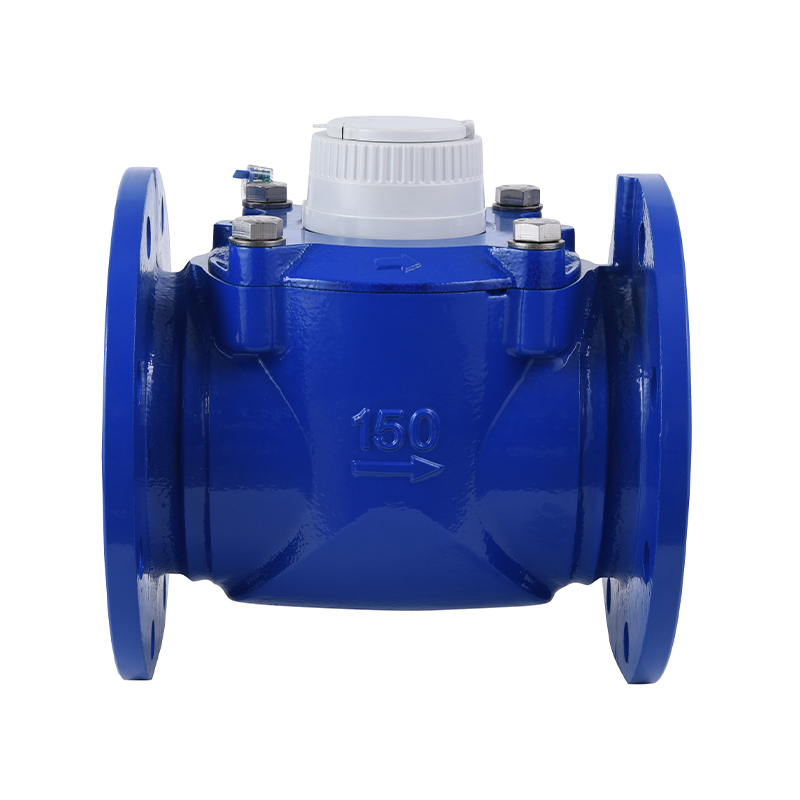
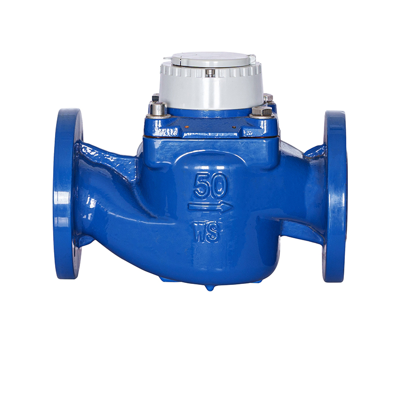
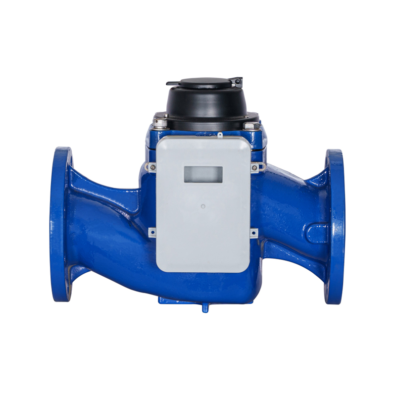
Managing high-volume fluid distribution across municipal water mains, industrial processing plants, and bulk non-urban supply lines requires specialized metrological hardware engineered to process massive volumetric flows without introducing steep energy losses. The industrial-grade WPD water meter serves as the primary technical standard for tracking these high-capacity lines, operating explicitly on the mechanical principles of a Woltman parallel turbine. By aligning the impeller shaft completely parallel to the incoming fluid stream, this specialized instrument captures broad volumetric variations with extreme precision, delivering consistent billing data and operational insights while maintaining a nearly unrestricted flow path.
Kinematic Principles of the Woltman Parallel Turbine Mechanism
The fundamental engineering feature that defines a WPD water meter is the orientation of its internal kinetic components. Unlike standard vertical-axis turbine meters (often designated as WPH configurations) where fluid must change direction to strike the impeller blades, the WPD architecture positions the helix rotor axis perfectly parallel to the pipeline centerline.
As pressurized water enters the cast-iron bore of the meter body, it moves straight through without any sharp bends or restrictive drops in direction. This straight-line flow profile hits the helical blades of the balanced rotor, spinning it at a speed that directly matches the velocity of the passing fluid. Because the water does not have to alter its path, the configuration maintains a remarkably low pressure loss. This design lets municipal operators push higher volumes of water through the system using less pumping energy, which translates to direct operational cost savings.
Hydrodynamic Bearing Relief and Long-Term Stability
To prevent mechanical wear during periods of extreme high-velocity or constant peak flows, high-grade WPD systems incorporate a patented hydrodynamic bearing relief design. As flow velocity climbs, the changing pressure fields around the specially molded plastic rotor generate a subtle forward lift. This aerodynamic lift counters the physical push of the water stream, reducing the friction load on the tungsten carbide thrust bearings to almost zero. This mechanism extends the operating lifespan of the calibrated core, ensuring the meter retains its strict factory calibration across years of uninterrupted field service.
Hermetic Encapsulation and Register Ingress Protection
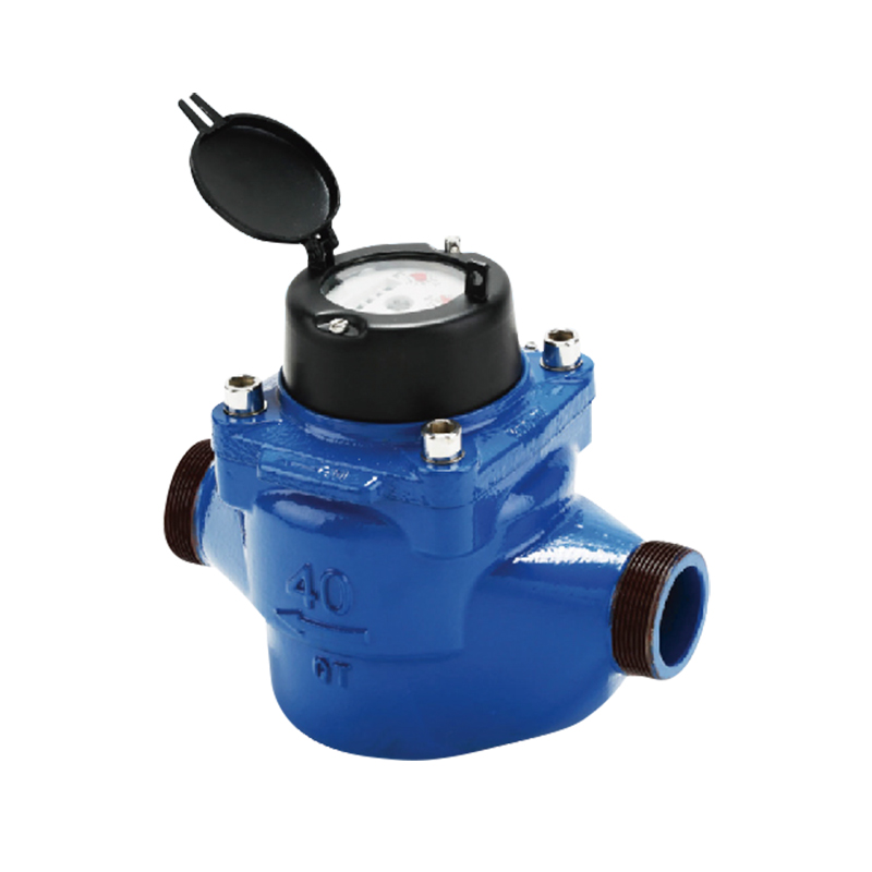
The raw mechanical spinning of the parallel rotor must be reliably converted into readable numeric data without exposing the counting gears to water damage, sediment coating, or chemical corrosion. WPD meters achieve this isolation by utilizing a completely dry-dial register configuration.
The spinning movement of the rotor is transmitted up to the sealed dial module through a high-strength magnetic coupling, bypassing the need for any physical shafts or seals that could wear out and leak. The register assembly itself is protected inside a heavy glass-and-copper container, commonly referred to as a "copper can" enclosure. This heavy-duty shielding gives the counting module an IP68 ingress protection classification. This hermetic seal keeps out dust, blocks condensation, and ensures the dial face remains perfectly clean and readable, even if the installation pit floods completely under up to 2.0 meters of standing water.
360-Degree Rotatable Dials for Field Auditing
To simplify manual data collection in tight underground utility vaults, the entire upper register housing can be unlatched and rotated a full 360 degrees without disrupting the internal magnetic drive connection or breaking official verification seals. This design allows field technicians to easily position the odometer wheels toward the access hatch, minimizing reading errors during routine physical audits.
Metrological Specifications and Volumetric Performance Boundaries
Correctly deploying a bulk WPD meter requires matching the nominal flange diameter to the specific continuous and peak flow patterns of the utility system. Implementing a bulk parallel meter in an environment dominated by trickle flows will result in significant under-billing, as the parallel rotor requires a minimum kinetic threshold to overcome initial starting inertia.
The table below outlines the standard flow rate categories, dimensional lengths, and overload tolerances for flanged WPD bulk water meters operating under standard ISO 4064 metrological parameters:
| Nominal Diameter (DN) | Minimum Flow Rate ($Q_1$) | Continuous Flow Rate ($Q_3$) | Overload Peak Flow ($Q_4$) | Standard Body Length (L) |
|---|---|---|---|---|
| DN 50 (2-Inch Line) | 0.20 Cubic Meters / Hour | 40.0 Cubic Meters / Hour | 50.0 $m^3/h$ | 200 mm |
| DN 80 (3-Inch Line) | 0.32 Cubic Meters / Hour | 63.0 Cubic Meters / Hour | 78.75 $m^3/h$ | 225 mm |
| DN 100 (4-Inch Line) | 0.32 Cubic Meters / Hour | 100.0 Cubic Meters / Hour | 125.0 $m^3/h$ | 250 mm |
| DN 150 (6-Inch Line) | 0.79 Cubic Meters / Hour | 250.0 Cubic Meters / Hour | 312.5 $m^3/h$ | 300 mm |
| DN 200 (8-Inch Line) | 2.50 Cubic Meters / Hour | 400.0 Cubic Meters / Hour | 500.0 $m^3/h$ | 350 mm |
Smart Telemetry Modules and Remote Advanced Metering Infrastructure
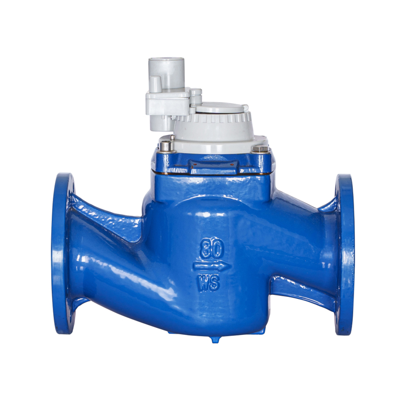
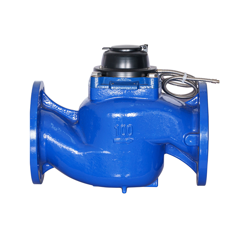
Modern water management relies on data-driven, real-time tracking, moving away from manual, visual readings. WPD meters natively adapt to this digital shift by incorporating specialized modulator discs and sensor ports built right into the register dial face.
The mechanical register features an embedded target wheel that spins below a reaction-free electronic scanning sensor. This electronic capture system outputs pulse data without applying any magnetic drag or friction to the counting needles, preserving the meter's high precision even at low flow rates. Technicians can snap automated data capture modules—such as LoRaWAN, Wireless M-Bus, or cellular NB-IoT transmitters—directly onto the meter frame without breaking official utility verification seals.
These smart transmitters log and broadcast water consumption data at set times daily, sending the information directly to centralized utility databases. This automated data stream allows operators to spot system anomalies quickly. For instance, if a large commercial facility shows high, continuous water usage in the middle of the night when operations are shut down, the system flags a likely hidden line break, helping the team respond fast to minimize water loss and protect infrastructure.
Piping Engineering, Straight-Run Limits, and Flow Conditioning
To achieve an accuracy rating of within +/-2% under continuous flow conditions, the water entering the parallel turbine must be free from severe swirl distortions, uneven velocity profiles, and air pockets. When water passes through structural fittings like pipe bends, T-junctions, or centrifugal pumps, it develops a chaotic spiral motion that can skew flow data if the meter is placed too close to the source of turbulence.
To address this, piping designers follow strict straight-run guidelines upstream and downstream from the meter flanges. A standard configuration requires an unrestricted straight pipe section measuring at least 10 times the nominal pipe diameter (10D) upstream from the meter, paired with a straight section of at least 5 times the pipe diameter (5D) downstream. These straight pipe runs give turbulent swirls space to flatten out naturally, ensuring a clean, parallel flow profile hits the turbine blades for accurate measurement.
Integrated Swirl-Reducing Inlet Geometry
Advanced versions of the WPD series feature built-in swirl-reducing vanes cast directly into the intake chamber. This internal layout actively breaks up spinning fluid eddies right as they enter the meter body, allowing the unit to meet strict OIML R49 accuracy rules even in tight spaces where full 10D straight pipe runs are impossible.
Field Installation Blueprint and Flange Alignment Protocol
Installing a heavy WPD bulk water meter into a main distribution line requires following careful mechanical procedures. Poor alignment or improper bolt tensioning can distort the meter body, damage internal components, or cause flange seals to blow out under pressure.
- Verify Pipeline Directional Paths: Check the cast-iron exterior body to find the cast flow arrow. The meter must be oriented so that the parallel turbine faces directly into the incoming water stream; installing a meter backward blocks the register from tracking usage and can damage the internal gearing.
- Purge the Main Delivery Line: Run the primary pump system at full capacity prior to dropping the meter into place. This high-volume flush clears out welding slag, rust scale, dirt clumps, or gravel left inside the pipe during construction, preventing debris from striking and fracturing the polymer turbine blades.
- Seat Gaskets and Cross-Torque Bolts: Fit premium steel-reinforced EPDM gaskets cleanly between the mating flange faces. Insert high-tensile fasteners through the holes and use a calibrated torque wrench to tighten the nuts in a progressive star-pattern sequence, ensuring even compression to prevent body warping and leaks.
- Maintain a Full-Pipe Hydraulic State: Position the meter line layout at a low point in the piping network, or install a raised U-bend downstream from the discharge port. This height difference ensures the meter barrel remains completely flooded with water during operation; if the pipe runs partially empty, the turbine will under-read consumption values significantly.
- Install Upstream Strainer Support: Mount a dedicated matching strainer component upstream from the meter inlet when drawing water from open canals, rivers, or shallow wells. The strainer mesh catches floating weeds, snails, and wood debris, protecting the turbine core from jamming.
Field Diagnostics and Replaceable Metrological Element Logistics
Even with a rugged design, a bulk water meter handling raw water can eventually experience mineral scaling, particulate wear, or mechanical blockages that cause its measurement accuracy to drift over time.
To minimize maintenance costs and eliminate long system shutdowns, WPD meters are built around a modular core design. The entire turbine system, including the rotor, thrust bearings, flow vanes, and sealed register head, is assembled as a single removable metrological unit.
When a meter fails a field accuracy check, maintenance teams do not need to cut the heavy cast-iron body out of the pipeline. Instead, technicians simply isolate the line using gate valves, bleed off the internal water pressure, and unbolt the top main cover plate. The entire internal measuring core can then be lifted out cleanly as a single piece. The team can slip a fresh, pre-calibrated, MID-compliant core module back into the existing iron housing, torque down the cover bolts, and restore full service in under an hour, significantly cutting field labor costs and keeping the system running efficiently.