
 عربى
عربى

The Fluid Dynamics and Metrological Advantages of Parallel Turbine Integration
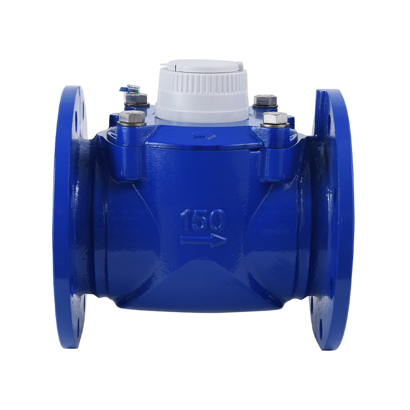
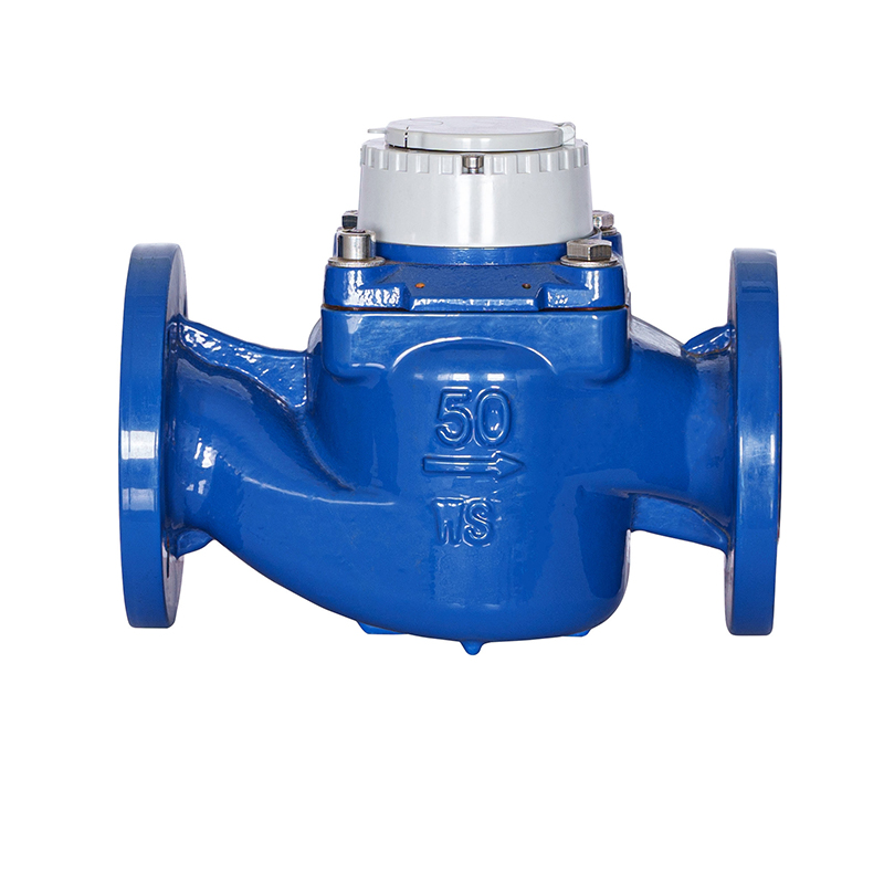
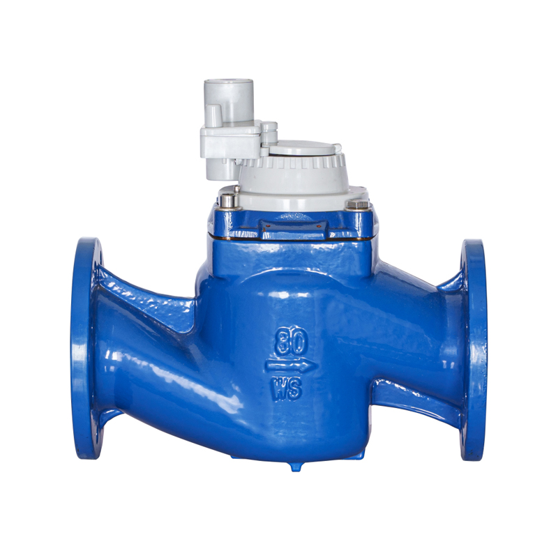
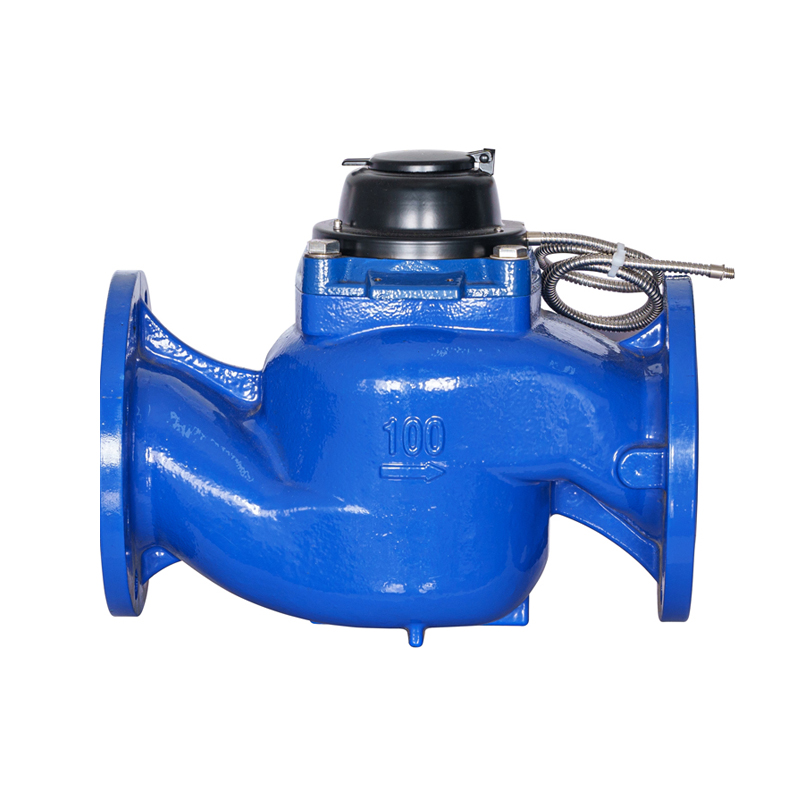
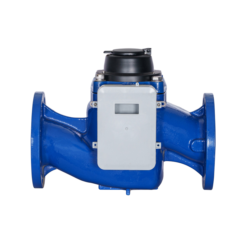
Deploying a high-performance wpd water meter (configured as a Woltman Parallel type bulk fluid device) provides industrial process networks, municipal mainlines, and water treatment utilities with an advanced mechanical solution for measuring vast volumetric quantities of water across fluctuating flow conditions. By arranging a hydrodynamically balanced helical turbine wheel axially and perfectly parallel along the geometric centerline of the liquid stream, this design minimizes fluid redirection. This optimized internal architecture establishes a highly responsive kinetic measurement profile that delivers a head loss reduction of up to 60% compared to conventional vertical-axis turbine configurations. This structural advantage ensures steady delivery pressures across bulk transmission mains, allowing a standard DN150 meter to reliably handle peak overload flow surges up to 350 cubic meters per hour without risking blade fatigue or systemic accuracy drift.
In modern high-volume water networks, engineering bulk flow lines requires a balancing act between capturing low-velocity consumption and surviving sudden hydraulic surges. Main water lines often run under intense structural pressures and carry significant kinetic force. Standard multi-jet or domestic displacement meters rely on internal baffles and restrictive channels to force fluid against the measuring component, making them highly prone to immediate mechanical damage when hit by heavy water hammer shockwaves. Transitioning to a parallel-axis Woltman design resolves these network vulnerabilities by keeping the internal flow tunnel open and straight. This enables large volumes of water to pass through with minimal restriction, protecting the internal components from high-velocity friction and structural deformation.
Parallel Hydrodynamics and Dry-Dial Magnetic Transmissions
The long-term performance and reading accuracy of a WPD-class utility meter depend on the exact alignment of its helical blades and the complete sealing of its dry-dial register configuration.
Symmetric Axial Fluid Loading Mechanics
In a parallel Woltman structure, the oncoming water column strikes the entire surface of the helical rotor blades evenly. This uniform distribution eliminates the asymmetrical side-loading forces that typically wear down vertical-axis impellers. Supported by precision synthetic sapphire or tungsten carbide pivot pins, the rotor creates a natural hydrodynamic lift as it spins. This lift unloads the bearing surfaces, significantly reducing friction losses and allowing the meter to stay highly accurate at low starting flow velocities.
Hermetically Protected Vacuum Register Cells
To keep suspended sand, dissolved lime scale, and moisture from clouding or jamming the odometer wheels, the mechanical gear train is split by a solid pressure wall. The wet-side turbine shaft spins an array of high-coercivity rare-earth magnets, projecting magnetic lines of force through a non-magnetic stainless steel plate to turn a matching magnet set inside the dry, vacuum-sealed copper register capsule. This complete isolation ensures the register digits stay clear and readable, safe from mineral scaling or freezing over decades of field service.
Comparative Design Evaluation: WPD Parallel Woltman Meters vs. Single-Jet Mechanical Meters
Selecting the proper industrial bulk flow tracking platform requires analyzing maximum weight capacities against induced head loss, particulate tolerance, and installation flexibility. The comparative table below details the performance boundaries between parallel Woltman systems and traditional single-jet designs.
| Technical Engineering Factor | WPD Parallel Woltman Water Meter | Standard Single-Jet Utility Meter |
|---|---|---|
| Induced Head Loss (Pressure Drop) | Minimal (Straight-through bore leaves flow unrestricted) | High (Internal nozzle restrictions cause pressure drops) |
| Overload Flow Surge Capacity | Exceptional (Handles continuous peak rates up to 200% Q3) | Poor (High-velocity surges cause bearing failure) |
| Particulate Suspended Tolerance | High (Open measuring channel allows fine debris bypass) | Low (Debris easily clogs or jams the internal jet nozzle) |
| Installation Axis Versatility | Universal (Maintains full accuracy in horizontal or vertical lines) | Restricted (Accuracy drops severely when tipped vertically) |
| Interchangeable Measuring Inserts | Standardized (Core mechanism lifts out for easy calibration) | None (Requires replacing the entire outer cast body) |
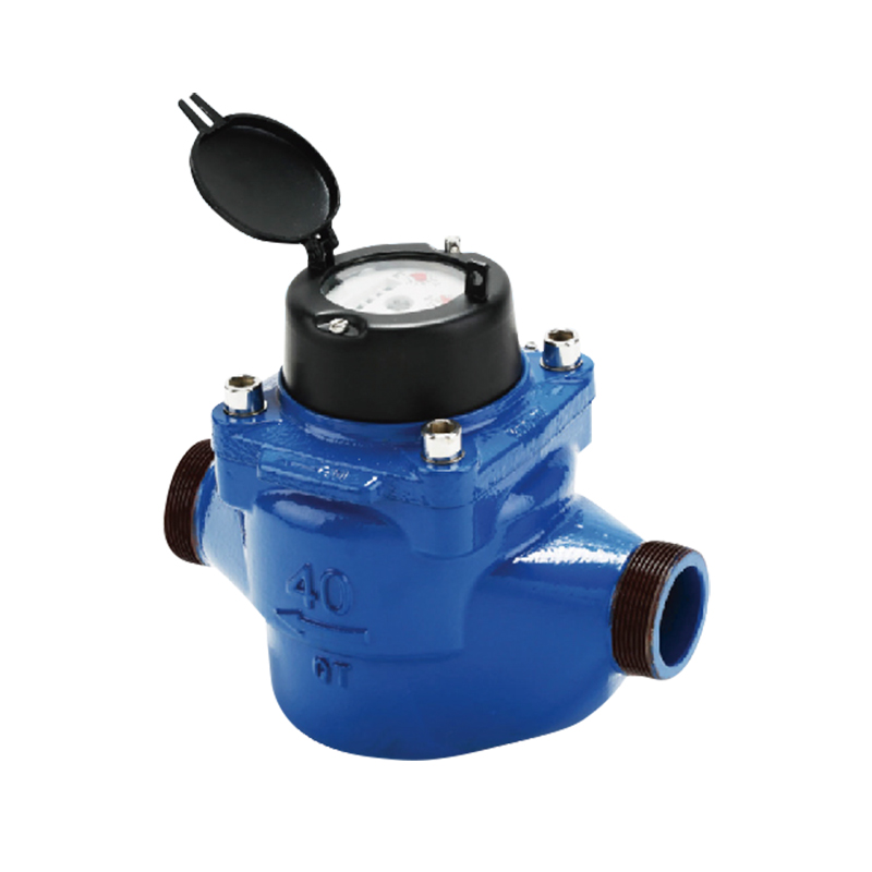
The technical data comparison shows why modern facility managers favor parallel-axis designs for bulk monitoring nodes. Single-jet mechanical meters provide excellent cost-efficiency and high sensitivity for low-diameter domestic properties, but they introduce significant restrictions into large pipelines. When subjected to continuous industrial water usage, a single-jet's off-center loading patterns rapidly accelerate bearing wear, causing the meter to under-register flow totals after a few months. WPD parallel water meters avoid these wear patterns by using an axial design, allowing high-volume fluid streams to pass straight through while maintaining uniform rotor balance.
Advanced Output Signaling and Intelligent Smart-Grid Integration
Modern parallel Woltman meters feature built-in electronic signaling options to integrate directly with factory automation systems and municipal telemetry networks.
- Dual pulse-generating Reed Modules: The outer register housing is built to accept plug-and-play magnetic pulse sensors. As the internal wheels spin, the sensor broadcasts clean digital pulse closures (e.g., 1 pulse per 100 liters) to remote batch controllers or digital flow loggers.
- Inductive Non-Magnetic Encoders: For high-frequency billing grids, non-magnetic inductive scanning wheels track flow direction in real time. This system captures instantaneous flow profiles and instantly triggers alarms for backward pipeline flow or tampering.
- Wireless NB-IoT and LoRaWAN Modems: The meter shroud can be upgraded with integrated low-power wide-area radio transmitters. These modems broadcast hourly consumption data to cloud interfaces, removing the need for manual site inspections and enabling predictive leak detection across long networks.
Step-by-Step Flow Profile Stabilization and Mounting Sequence
Because asymmetric fluid velocities, upstream bends, and pumping equipment can distort the water column and affect measurement accuracy, field crews follow a disciplined installation sequence.
- Upstream Straight Run Assessment: Review the piping layout to ensure a straight section of pipe at least 3 to 5 times the nominal pipe diameter (3D - 5D) upstream from the meter inlet flange, helping smooth out fluid swirling patterns caused by nearby fittings.
- Downstream Space Allocation: Ensure a straight section of pipe spanning at least 2 times the nominal pipe diameter (2D) downstream from the meter outlet connection to prevent fluid stall zones from creating backpressure ripples on the rotor.
- Pipeline Flushing and Slag Purge: Before dropping the meter body into position, flush the pipeline run at high speed to clear loose welding slag, stone debris, and rust scale that could damage the spinning turbine blades.
- Flange Alignment and Bolt Securing: Set the cast-iron housing into the line, verifying the arrow on the body matches the actual water flow direction. Place high-density rubber gaskets between the flanges and tighten the steel bolts in a cross-star sequence.
- Gradual Hydrostatic Line Charging: Open the upstream isolation valves slowly over 60 to 90 seconds to fill the internal meter chamber with water. Avoid sudden pressure spikes, which can spin a dry turbine past its speed limits and shear the drive pins.
Mitigating Fluid Velocity Skew and Managing Entrained Air Voids
While heavy-duty WPD water meters are built to handle tough industrial environments, fluid vortices and pipeline air pockets can distort calibration over time if left unmanaged.
Preventing Air Pocket Over-Registration Errors
Air pocket tracking errors occur when large air bubbles accumulate at high points in a pipeline. Because compressed air moves much faster than liquid water, these air pockets spin the parallel turbine at extreme speeds, leading to falsely inflated consumption figures. To keep metrics accurate, system designers should install automatic air venting valves directly upstream from the meter body and avoid placing the meter at the highest point of a pipe layout, ensuring the measuring chamber stays completely filled with liquid.
Controlling Asymmetrical Velocity Profiling Skew
Placing a parallel Woltman meter directly after a half-closed butterfly valve can warp the water velocity profile, forcing high-speed streams along one side of the inner chamber. This uneven loading applies twisting stress to the rotor shaft, accelerating bearing wear and skewing measurement accuracy. Plant engineers can prevent this velocity distortion by installing a honeycombed flow straightening plate inside the upstream pipe section, ensuring a balanced, symmetric water stream strikes the parallel rotor blades.