
 عربى
عربى

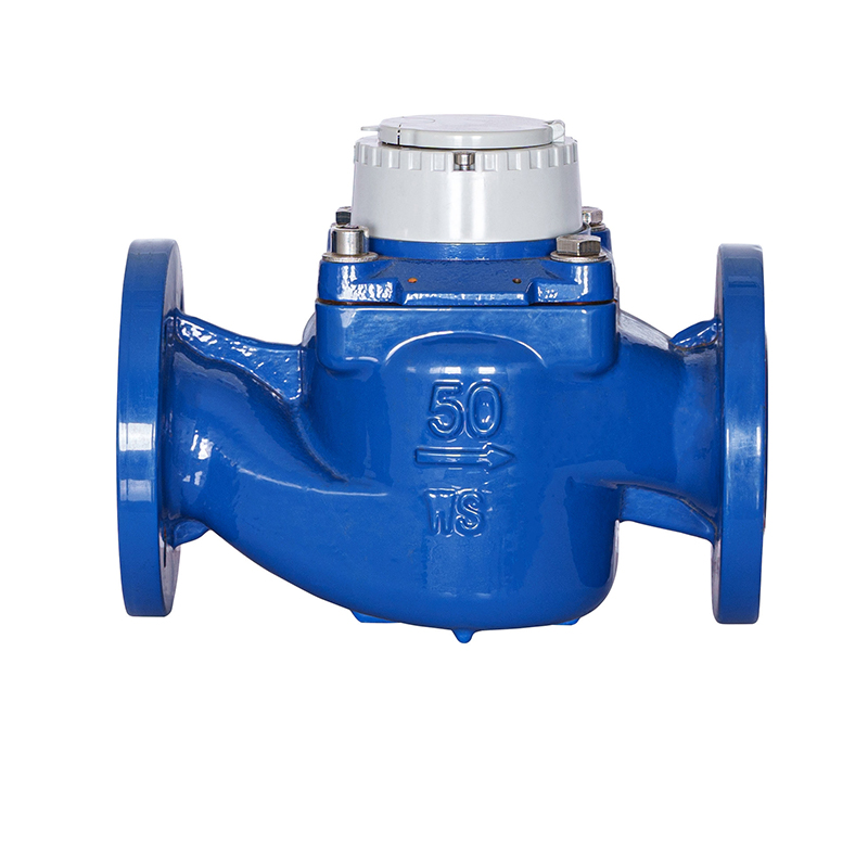
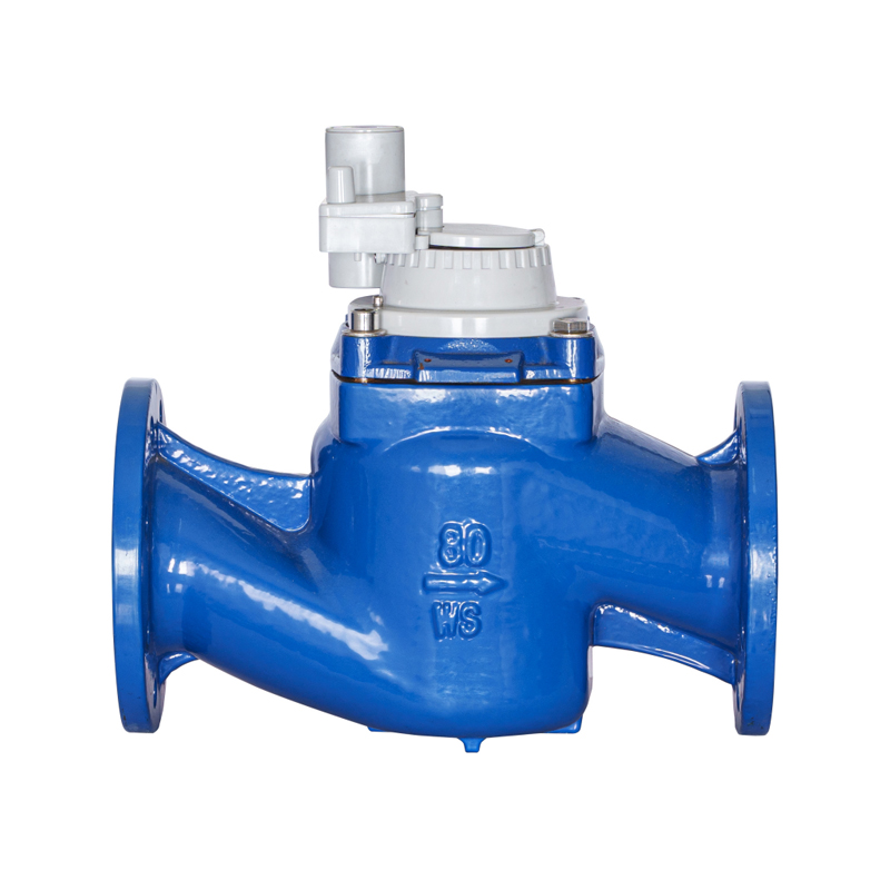
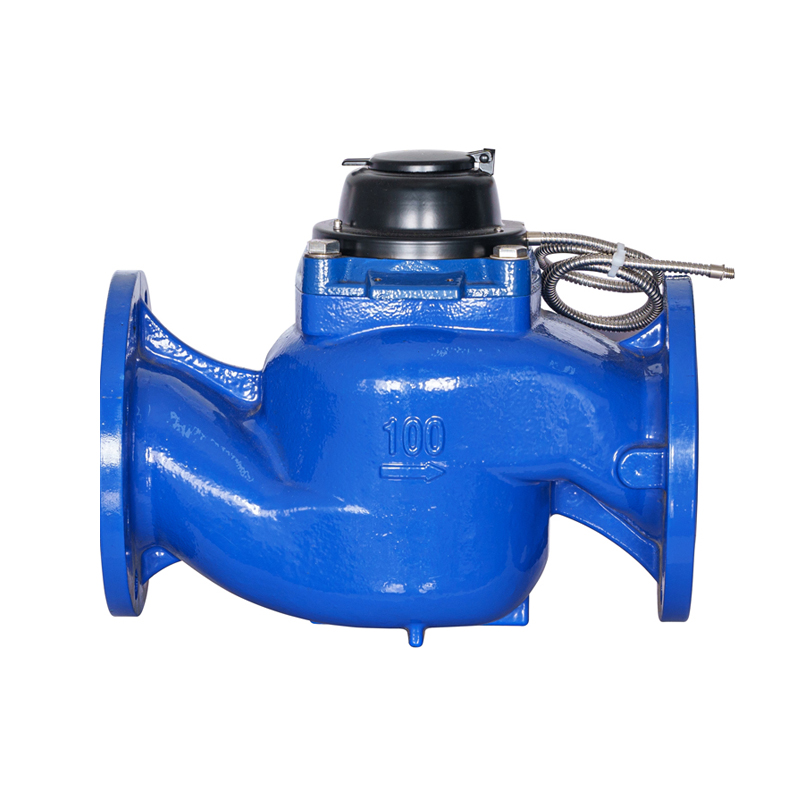
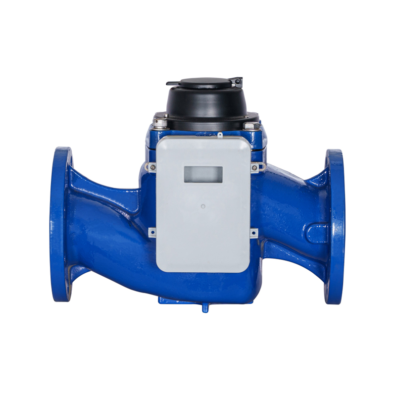
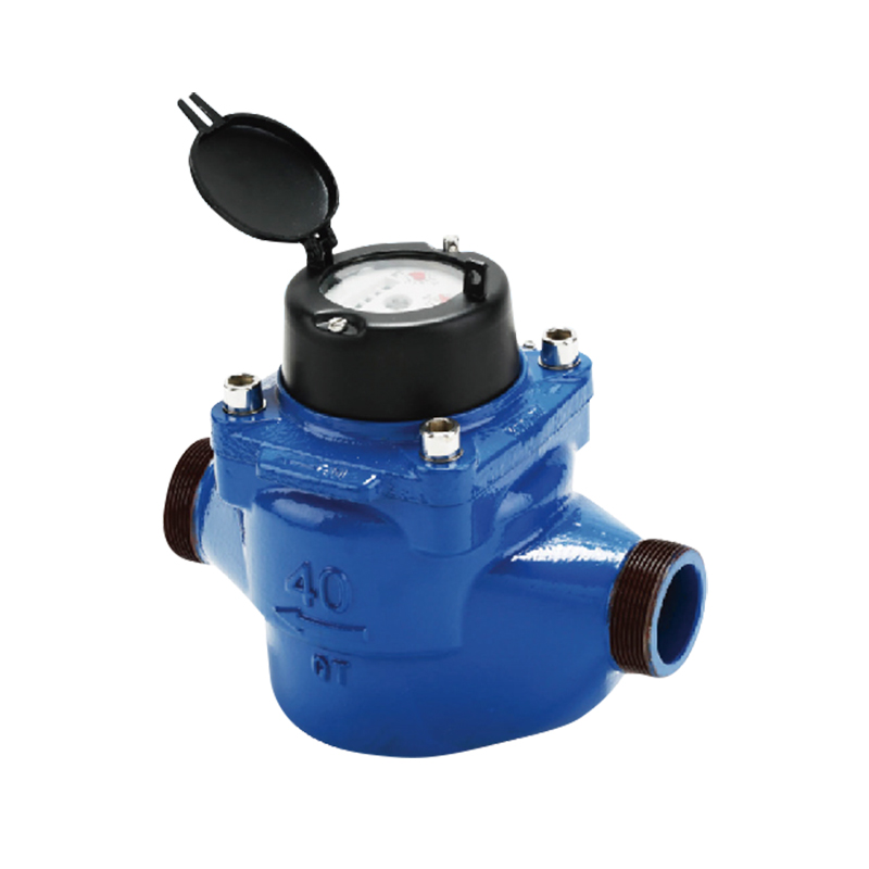
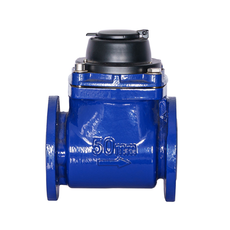
Municipal water distribution networks, industrial manufacturing plants, and agricultural irrigation systems rely on the WS vertical spiral wing water meter to achieve precise, high-capacity fluid measurement under volatile flow conditions. Unlike conventional horizontal Woltman meters, the WS design features a vertical impelling axis perpendicular to the fluid pipeline flow vector. This structural orientation optimizes hydrodynamic kinetic energy capture, allowing the device to measure high-velocity bulk water volumes accurately while minimizing internal friction, mechanical wear, and upstream pressure losses.
The integration of a vertical spiral wing design solves several foundational problems plaguing volumetric network management. Traditional horizontal turbine meters frequently suffer from rapid bearing degradation when subjected to particulate debris or sudden water hammer forces. The WS vertical geometry redistributes hydraulic thrust load vectors across a specialized magnetic suspension or tungsten carbide pivot assembly, delivering excellent measurement responsiveness, long-term calibration stability, and extended maintenance intervals across demanding municipal and commercial infrastructures.
Hydrodynamic Principles and Internal Kinetic Engineering
The mechanical precision of a WS vertical spiral wing water meter depends entirely on its specific fluid dynamics profile. As water enters the meter's intake port, an internal guiding mechanism shapes and accelerates the column of liquid, directing it smoothly toward the helical impelling blades.
Vertical Impeller Orientation and Thrust Mitigation
By orienting the spiral wing assembly vertically, the incoming horizontal fluid flow is redirected upward through a curved internal chamber before exiting the discharge side. This transition creates a hydrodynamic lift effect that partially counters the physical weight of the moving turbine runner. This lift reduces the net downward force exerted on the lower pivot jewel assembly, ensuring that the meter remains highly sensitive to minimal fluid movement while retaining exceptional structural durability during maximum peak flow volumes.
Magnetic Drive Transmission Systems
To prevent water from leaking into the delicate register gear assembly, the WS meter uses a contactless magnetic coupling system. High-coercivity permanent magnets mounted inside the wet-running vertical impeller shaft transmit rotational counts across a solid, pressure-sealed stainless steel isolation plate to a matching set of magnets inside the dry counter register. This isolation protects the tracking gears from particulate scaling, mineral buildup, and chemical oxidation, preserving uninterrupted transmission accuracy over a multi-decade operational lifespan.
Comparative Structural Metrics: WS Vertical vs. Horizontal Woltman Designs
Selecting bulk water measurement hardware requires a thorough assessment of technical metrics, installation space limits, and long-term fluid handling needs. The data below contrasts the operational boundaries and performance profiles of the WS vertical design against standard horizontal Woltman configurations.
| Technical Specification Metric | WS Vertical Spiral Wing Meter | Horizontal Woltman Turbine Meter |
|---|---|---|
| Minimum Start-Up Flow Rate (Q1) | Superior Sensitivity; roughly 40% lower start threshold | Moderate Sensitivity; requires higher initial velocity |
| Pressure Loss Coefficient (ΔP) | Extremely Low (< 0.03 MPa at nominal flow) | Moderate (< 0.06 MPa due to internal path limits) |
| Required Straight Pipe Run (Up/Down) | Highly Compact; requires 5D upstream / 2D downstream | Extended; requires 10D upstream / 5D downstream |
| Bearing Wear Velocity Profile | Low; balanced by hydraulic lift forces | High; constant horizontal thrust load friction |
| Debris Tolerance Threshold | High; self-cleaning vertical particle shedding | Moderate; horizontal shafts can trap fiber strands |
Material Composition and Structural Integrity Protocols
To safely withstand the high working pressures of main distribution lines, WS water meters are built using durable materials and corrosion-resistant surfaces. Mismatching housing compounds with fluid chemistry can result in pinhole leaks and structural failure under load.
Ductile Iron Housing with Fusion-Bonded Epoxy Finish
The outer pressure shell is typically cast from high-tensile ductile iron (GGG40/50 grade), providing the structural capacity to handle continuous working pressures up to 1.6 MPa (16 Bar) or 2.5 MPa (25 Bar) without deformation. The casting is finished inside and out with an electrostatic fusion-bonded epoxy powder coating at a thickness of 200 to 300 microns. This layer isolates the raw iron from corrosive soil chemistry and dissolved oxygen in the water supply.
Polymer Core Components and Exotic Alloy Pivots
The vertical spiral wing impeller is molded from high-density engineering polymers reinforced with glass fiber. This material resists chemical scaling and prevents balance issues up to temperatures of 50 degrees Celsius for cold-water variants. The rotor shaft rotates on a precision-ground tungsten carbide pin seated against a synthetic sapphire jewel bearing, lowering the mechanical friction coefficient to guarantee accurate flow tracking over long-term usage.
Smart Data Integration and Pulse Output Capabilities
Modern utility systems require advanced remote reading capabilities, moving away from manual, on-site register inspections. The WS vertical meter integrates direct digital data output modules to support automated meter reading (AMR) and advanced metering infrastructure (AMI) networks.
- Reed Switch and Hall-Effect Pulse Transmitters: The dry-dial counter face can be equipped with detachable pulse sensor modules. These transmitters generate a digital pulse at fixed volume increments (e.g., 1 pulse per 100 liters or 1 pulse per 1,000 liters), sending flow data to external data loggers without needing to modify the main meter body.
- Photoelectric Direct-Reading Registers: Advanced options feature built-in photoelectric sensors that read the mechanical wheel positions directly. This eliminates pulse counting errors caused by line noise or contact bounce, allowing the system to transmit an exact electronic reading that matches the physical counter numbers via M-Bus or RS-485 Modbus connections.
- Wireless IoT Network Adaptation: By wiring the meter output directly into low-power wide-area network (LPWAN) nodes, flow telemetry data can be transmitted long distances via NB-IoT or LoRaWAN protocols. This allows municipal utility operators to monitor real-time consumption and identify pipeline leaks instantly from a centralized control station.
Step-by-Step Installation Protocols for Hydraulic Accuracy
Ensuring the accurate calibration and ongoing field precision of a bulk water meter depends heavily on proper physical installation. Deviating from standard pipe layout guidelines can create internal fluid turbulence, leading to incorrect consumption data.
- Pipeline Flushing and Debris Clearance: Prior to lowering the meter body into position, flush the upstream pipe section thoroughly to clear away welding slag, sand, rocks, and internal rust scale. Leaving these particles in the line can score the polymer impeller blades or clog the inlet flow straightener.
- Horizontal Orientation Alignment: Position the WS meter body horizontally along the pipeline axis, making sure the dry dial counter face points directly upward. Installing the unit at a tilt compromises the vertical balance of the internal spiral wing axis, increasing friction on the side walls and throwing off low-flow measurement accuracy.
- Verify Directional Flow Vectors: Check that the directional arrow cast into the outer ductile iron body matches the actual path of fluid travel through the pipe network. Installing a meter backward reverses the internal gear train rotation and disrupts proper flow measurement.
- Secure Proper Straight Pipe Clearances: Maintain an unbroken straight run of pipe measuring at least 5 pipe diameters upstream and 2 pipe diameters downstream from the meter flanges. Avoid installing control valves, check valves, or sharp elbows inside this clearance zone to prevent turbulent eddy currents that compromise reading accuracy.
- Air Venting and Hydrostatic Charging: Open valves slowly downstream from the meter to purge trapped air pockets from the line. Allowing air to rush through the system at high speeds can cause the vertical impeller to over-spin, potentially shattering the polymer blades or causing permanent bearing damage.
Field Verification, Calibration Validation, and Preventive Maintenance
Industrial and municipal water meters operate continuously in demanding environments. Over long periods of time, exposure to dissolved minerals, slight pH variations, and suspended micro-sediments can cause subtle measurement drift.
To ensure compliance with municipal accuracy standards, high-volume meters should undergo a calibration validation check every 24 to 36 months. This field test uses a portable master meter or a calibrated volumetric container hooked up to the main line's testing port, validating reading precision across three main test zones: the minimum start flow (Q1), transitional flow (Q2), and maximum continuous overload flow (Q3).
A key service benefit of the WS vertical spiral wing design is its modular cartridge build. The entire internal measurement assembly—including the vertical impeller, magnetic coupler, and gear train—can be lifted out from the main outer housing without removing the iron body from the pipeline. This design allows maintenance crews to quickly swap out worn internal cartridges, minimize system downtime, and verify reading accuracy without disrupting service to downstream industrial or residential users.