What unique engineering benefits does the detachable structure and low pressure loss design of the horizontal spiral wing water meter provide for utility network maintenance and operational efficiency?
The horizontal spiral wing water meter stands as a sophisticated instrument designed for the accurate registration of the total volume of water passing through a tap water pipeline. Its design philosophy centers on achieving high reliability and easy maintenance while strictly complying with the demands of modern water utility operations. A specialized horizontal spiral wing water meter manufacturer and factory has focused on refining this model to maximize efficiency and longevity in field applications. This particular design integrates a powerful horizontal spiral wing mechanism with a practical, detachable structure, providing substantial operational advantages over conventional fixed meters.
Advanced Mechanical Innovation and Field Maintenance Efficiency
The operational excellence and reduced cost of ownership associated with this metering technology are direct results of its innovative mechanical assembly. The design prioritizes minimal disruption during maintenance and a prolonged functional lifespan.
Structural Advantage of the Horizontal Spiral Wing Mechanism
The core measuring element, the horizontal spiral wing, is engineered to interact with the flow in a manner that ensures stability and accuracy across a wide range of flow rates. This arrangement offers distinct hydraulic and metrological advantages:
Optimized Flow Dynamics:
The horizontal orientation allows the flow of water to drive the spiral wing with high efficiency. The spiral shape of the wings ensures that the rotation is uniform and directly proportional to the volume of water passing through the measuring chamber.The design minimizes internal turbulence, leading to a straighter flow path, which is crucial for maintaining measurement precision, particularly in pipes where the flow profile may be less than ideal.
Reduced Pressure Loss:
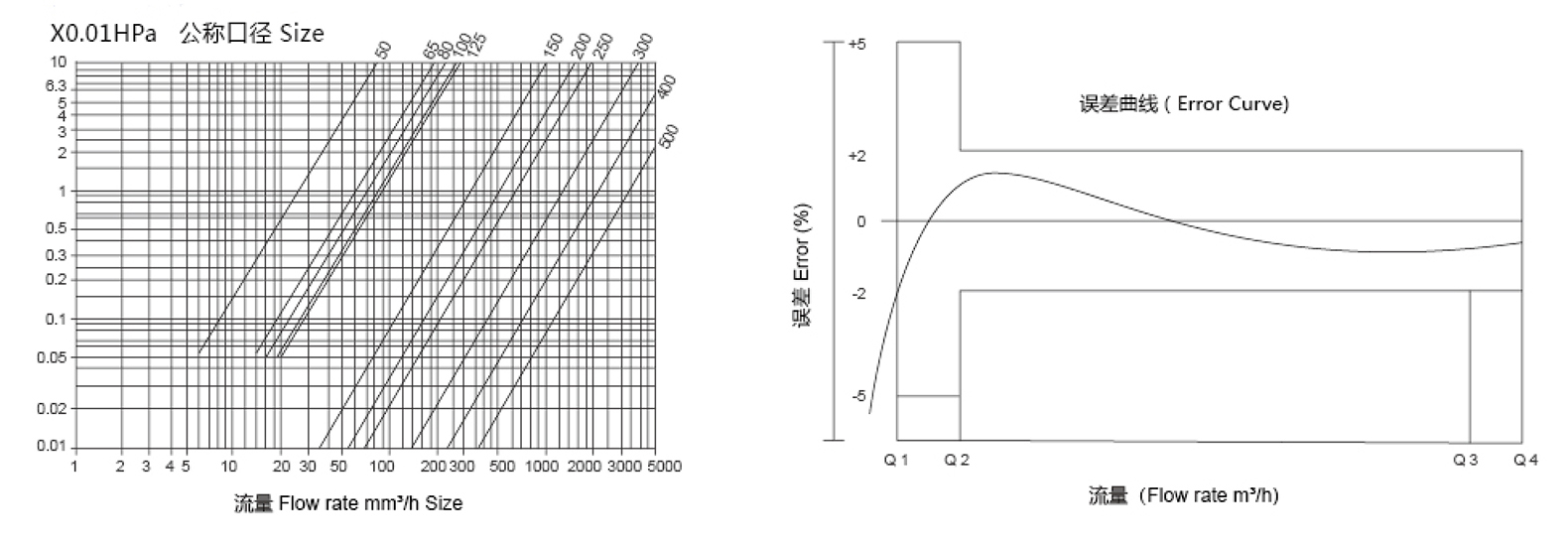
A key feature of the horizontal spiral wing water meter is its ability to significantly reduce pressure loss across the meter body. Reduced pressure loss ensures that the meter does not negatively impact the overall hydraulic performance of the water supply network.Lower pressure loss translates to energy savings in the pumping stations responsible for maintaining system pressure, leading to long term operational cost reductions for the utility provider.This is achieved through carefully optimized internal waterways, which are streamlined to prevent unnecessary frictional resistance, ensuring that a high volume of water can pass through the meter with minimal head reduction.
Sustained Measurement Accuracy:
The spiral wing is calibrated to provide consistent metrological performance, ensuring that the total amount of water flowing through the pipeline is recorded accurately over extended periods.Its robust construction is optimized for continuous operation within tap water environments, guaranteeing that the measurement mechanism maintains its integrity and calibration despite prolonged use.
The Strategic Benefit of Detachable Meter Architecture
Perhaps the most significant innovation in operational terms is the meter's detachable structure. This design choice revolutionizes the maintenance and repair protocols for large volume meters.
In Situ Repair Capability:
The meter does not need to be removed from the pipeline when servicing is required. This eliminates the necessity of cutting into the piping system, which is typically a labor intensive and time consuming process requiring specialized tools and highly skilled technicians.The main body of the meter, which is permanently flanged or connected to the pipe, remains fixed, acting as a flow conduit while the internal measurement components are serviced.
Ease of Movement Extraction:
The entire measuring movement, which includes the spiral wing, the gearing, and the register, can be easily pulled out as a single unit. This allows for rapid inspection or replacement.Technicians can perform movement replacement swiftly, dramatically reducing the duration of water service interruption for the end user or industrial facility. Reduced downtime is a critical performance metric for utility providers.
Streamlined Maintenance Workflow:
Instead of replacing the entire meter, the utility can simply swap the old internal movement with a newly calibrated or repaired movement. This process can be performed in the field quickly, minimizing the need for extensive training on complex piping work.The old movement can then be returned to a specialized workshop for repair and calibration, facilitating an efficient, circular inventory management system that saves money and resources.
Universal Measuring Mechanism:
The measuring mechanism of the horizontal spiral wing water meter has good universality. This means that the internal measuring cartridge is standardized across various meters within the product line or even across different sizes.This universality significantly reduces the need for large, complex spare parts inventories. Utilities only need to stock one or a few standardized movement types, reducing capital tied up in replacement parts and simplifying logistics.The interchangeability ensures that replacement and repair processes are standardized and foolproof, further enhancing maintenance efficiency.
How does the adaptability of the horizontal spiral wing water meter’s communication pointers ensure metrological integrity and seamless integration into diverse remote meter reading systems?
Beyond its mechanical superiority, the true value of the horizontal spiral wing water meter in the modern smart grid lies in its inherent adaptability for data communication and its resistance to external interference. This integration capability ensures that the high precision data recorded by the horizontal spiral wing is reliably and securely transmitted to central management systems.
Metrological Integrity and Advanced Remote Functionality
The design incorporates forward thinking features that allow the meter to evolve with the utility's technological requirements, ensuring longevity and relevance in a rapidly changing data landscape.
Focus on Tap Water Measurement and Fluid Compatibility
The horizontal spiral wing water meter is meticulously designed and calibrated for the measurement of tap water flowing through standard pipelines. This clear definition of its application scope is vital for guaranteeing the expected performance and lifespan.
Dedicated Tap Water Service: The internal materials and operating tolerances are optimized for the purity and temperature range typical of municipal water supply. This focus ensures the meter delivers maximum accuracy and resistance to wear under these specific conditions.
Exclusion of Corrosive and Contaminated Fluids: It is a fundamental operational guideline that this meter cannot be used for measuring sewage and corrosive liquids.Measuring corrosive liquids would lead to rapid degradation of the internal metallic or polymeric components, compromising the spiral wing’s calibration and potentially causing catastrophic failure.The presence of solids or contaminants in sewage would quickly foul the sensitive mechanical gearing and bearings, leading to premature wear, increased pressure loss, and inaccurate readings. Adherence to the tap water standard is paramount for maintaining the meter’s long service life.
Versatile Communication Pointer Reservations
A key feature enabling the meter's intelligent capabilities is the reservation of the communication interface directly on the register. This future proofs the investment by allowing utilities to choose the appropriate reading technology as their network evolves.
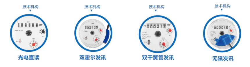
Magnetic Communication Pointers:
These utilize a traditional magnetic coupling or switch to generate a pulse or signal representing a specific volume of water passed.
Reliability: This method is well established, mechanically robust, and provides a clear digital signal output.
Configuration: Suitable for environments where a simple, reliable pulse output is all that is required for external data logging or simple remote transmission.
Non Magnetic Communication Pointers:
These are reserved for applications where meter tampering via external magnetic fields is a critical security concern.
Security: By utilizing optical, inductive, or other non magnetic sensing principles, the integrity of the measurement data is shielded from magnetic interference.
Data Integrity: This option ensures that the meter remains impervious to fraudulent attempts to slow or stop the meter's registration using external magnets, guaranteeing the security of utility revenue.
Future Proof Adaptability: The ability to reserve either magnetic or non magnetic communication pointers ensures that the core mechanical meter body is future proof. Utilities can deploy the mechanical meter today and configure the register with the appropriate reading technology—or upgrade it later—without replacing the entire in pipe assembly, thanks to the detachable structure.
Seamless Integration with Remote Transmission Devices
The reserved communication pointers allow for the configuration of various remote transmission devices according to different needs, fulfilling the mandate for automated meter reading (AMR) and advanced metering infrastructure (AMI).
Functionality of Remote Meter Reading:
The fundamental goal is to achieve the remote meter reading function. This capability allows utilities to collect consumption data without a physical site visit, dramatically reducing operating expenses.Remote data provides opportunities for more frequent billing cycles, improved cash flow management, and timely identification of network issues.
Configuration Flexibility:
Wired System Configuration: For dense urban areas or commercial installations, the meter can be configured with wired devices utilizing protocols such as M Bus or RS 485, enabling high speed, reliable data transmission over dedicated physical lines. This is often preferred for large industrial meters where data flow needs to be instantaneous and guaranteed.
Wireless System Configuration: For wider geographical coverage or less accessible installations, the meter can interface with wireless transmission modules, including technologies such as LoRa, Narrowband Internet of Things, or General Packet Radio Service. These modules transmit the meter data over radio frequencies or cellular networks.
Data Resolution and Granularity: The specific remote transmission device selected dictates the frequency and granularity of the data transmitted, allowing utilities to choose a solution that aligns with their desired level of network monitoring and operational insight.
Long Service Life Assurance:
The overall design—from the low friction internal workings to the robust, universal, and easily replaceable measuring mechanism—is intended to provide a long service life. This minimizes the frequency of total meter replacement, which represents a significant capital outlay.The combination of hydraulic efficiency, material resilience, and remote monitoring capabilities solidifies the horizontal spiral wing water meter as a reliable, cost effective, and technologically adaptable solution for water resource management in the contemporary utility landscape. The focus on durability and standardized components ensures that this investment delivers sustained, high quality measurement for decades.

 عربى
عربى


")


